Page 257 - 《应用声学》2025年第2期
P. 257

第 44 卷 第 2 期                朱志强等: 超声换能器的超构透镜设计与制备                                           517


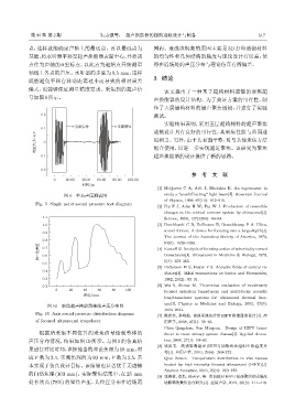
             点,这样就能确定声轴上的最远点。再以最远点为                            围内。造成该现象的原因主要是 3D 打印透镜材料
             基础,将水听器平移至超声换能器表面中心,并将该                           的均匀性和几何结构的精度与理论设计有误差,使
             点作为声轴的 0 坐标点,以此点为起始点开始测量                          得在近场处的声压分布与理论仿真有所偏差。
             轴线上各点的声压。水听器的步进为 0.5 mm,这样
                                                               3 结论
             既能避免平移台移动距离过小而导致的相对误差
             偏大,也能够保证测量精度要求。采集到的超声信
                                                                   该文提出了一种基于超构材料透镜的聚焦超
             号如图9所示。
                                                               声换能器的设计结构。为了验证方案的可行性,制
                                                               作了五层超构材料的超声聚焦透镜,并进行了实验
                 0.2                                           测试。
                                                                   实验结果表明,采用五层超构材料的超声聚焦
                               ԧ࠱ηՂ             ᧔ᬷηՂ
                 0.1                                           透镜设计具有良好的可行性,其聚焦性能与曲面透
               ႃԍܸ࠵/mV  0                                      镜相当。另外,由于其表面平整,易与其他聚焦方法

                                                               配合使用,以进一步实现超近聚焦。该研究为聚焦

                -0.1                                           超声换能器的设计提供了新的思路。

                -0.2
                                                                              参 考 文        献
                       0    20.00  40.00  60.00  80.00  100.00
                                  ௑ᫎ/ms
                                                                 [1] McQueen C A, Arlt J, Dholakia K. An experiment to
                           图 9  单点声压测试图                            study a “nondiffracting” light beam[J]. American Journal
                                                                   of Physics, 1999, 67(10): 912–915.
               Fig. 9 Single point sound pressure test diagram
                                                                 [2] Fry F J, Ades H W, Fry W J. Production of reversible
                                                                   changes in the central nervous system by ultrasound[J].
                  1.1                                              Science, 1958, 127(3289): 83–84.
                  1.0                                            [3] Burckhardt C B, Hoffmann H, Grandchamp P A. Ultra-
                                                                   sound Axicon: A device for focusing over a large depth[J].
                  0.9
                                                                   The Journal of the Acoustical Society of America, 1973,
                  0.8                                              54(6): 1628–1630.
                 ॆʷӑܦԍ  0.7                                      [4] Kossoff G. Analysis of focusing action of spherically curved

                                                                   transducers[J]. Ultrasound in Medicine & Biology, 1979,
                  0.6
                  0.5                                              5(4): 359–365.
                                                                 [5] Patterson M S, Foster F S. Acoustic fields of conical ra-
                  0.4
                                                                   diators[J]. IEEE transactions on Sonics and Ultrasonics,
                  0.3                                              1982, 29(2): 83–91.
                  0.2                                            [6] Wu X, Sherar M. Theoretical evaluation of moderately
                       0     20    40   60    80    100
                                                                   focused spherical transducers and multi-focus acoustic
                                   ᡰሏ/mm
                                                                   lens/transducer systems for ultrasound thermal ther-
                                                                   apy[J]. Physics in Medicine and Biology, 2002, 47(9):
                    图 10  聚焦超声换能器轴线声压分布图
                                                                   1603–1621.
               Fig. 10 Axis sound pressure distribution diagram
                                                                 [7] 陈庆春, 孙明灿. 泌尿系统治疗用 HIFU 换能器的设计 [J]. 应
               of focused ultrasound transducer                    用声学, 2008, 27(1): 59–63.
                                                                   Chen Qingchun, Sun Mingcan. Design of HIFU trans-
                 根据所采集不同位置的采集信号绘制整体的                               ducer to treat urinary system disease[J]. Applied Acous-
             声压分布情况,结果如图 10 所示。与图 5 的仿真结                           tics, 2008, 27(1): 59–63.
                                                                 [8] 钱祖文. 高强聚焦超声 (HIFU) 加热活体组织中的温度分
             果进行对比可知,该换能器的理论焦深为58 mm,对
                                                                   布 [J]. 应用声学, 2010, 29(4): 269–272.
             应 F 数为 2.4,实测焦深约为 60 mm,F 数为 2.5,基                    Qian Zuwen.  Temperature distribution in vivo tissues
             本实现了仿真设计目标。该结果也显著优于无透镜                                heated by high intensity focused ultrasound (HIFU)[J].
                                                                   Applied Acoustics, 2010, 29(4): 269–272.
             的自然焦深(103 mm)。实际聚焦结果中,在25 mm
                                                                 [9] 张艳秋, 张浩, 孙天宇, 等. 剪切波对 HIFU 经颅聚焦形成温度
             处有次高 (78%) 的聚焦声压,其位置分布在近场范                            场影响的数值仿真研究 [J]. 应用声学, 2019, 38(3): 411–418.
   252   253   254   255   256   257   258   259   260   261   262