Page 155 - 《应用声学》2023年第6期
P. 155

第 42 卷 第 6 期               赵亚林等: 阵列式阻性消声器传递损失计算模型                                          1265


                 elimination of dissipative part, N f , was obtained by fitting the values of (TL s − TL 1)/TL 2 at all 1/1 octave
                                                                                             ′
                 bands. The modified model for calculating the theoretical value of noise elimination was TL t = TL 1 + TL 2 ·
                 N f . As an example, the calculation model of noise elimination for arrayed elements dissipative silencers with
                 different structures and sizes was established when the flow resistance of porous sound absorbing material
                              2
                 is 11425 Pa·s/m . It was testified by actual measurement results that the absolute error between modified
                 theoretical values and measured values of noise elimination at each octave band was less than 3 dB. When
                 the flow resistance of sound absorbing materials differs significantly from the values given in the example, the
                 calculation models of noise elimination should be determined based on the method proposed in this study.
                 Keywords: Arrayed elements dissipative silencers; Noise elimination; Calculation model; Belov formula
                                                               消声器单位长度消声量,消声量测量费时费力且投
             0 引言                                              入大,有必要发展阵列式消声器消声量计算模型。
                                                               阻性消声器消声量计算公式主要有 Belov 公式和
                 阵列式阻性消声器是近年来一种非常有潜力
                                                               Sabine公式   [5−6] 。Belov在声波导管理论基础上,假
             的新型消声器       [1] 。与片式阻性消声器相比,阵列式
                                                               设导管壁面为非刚性壁面且导管截面尺寸较小,推
             消声器吸声柱宽度和总吸声面积较大,具有更高消
                                                               导了适用于直管式消声器的消声量计算公式                      [7−9] 。
             声量,且具有通流面积大、气流阻力小、气流再生噪
                                                               Sabine 建立了实际管道系统,通过测量不同长度、
             声和压力损失小等优点            [2] ,在大风量的地铁风亭、
                                                               尺寸和形状的管道中声衰减量,根据实验数据总结
             空冷器、冷却塔和航空发动机试车间等场所得到广
                                                               出直管式消声器消声量计算公式                 [10−11] 。Belov 公
             泛应用   [3−4] 。
                                                               式和 Sabine 公式均针对单通道的直管式阻性消声
                 消声器消声量通常采用传递损失 (Transmis-
                                                               器,不适用于横截面尺寸较大且气流通道彼此连通
             sion loss, TL) 进行评价。TL 指消声器入口端声
                                                               的阵列式阻性消声器。
             功率级和出口端声功率级的差值,其可通过测量
                                                                   本文根据阵列式消声器结构特点,在合理划分
             或理论计算确定。阵列式消声器几何尺寸通常较
                                                               消声单元基础上,建立了半理论半经验消声量计算
             大,《声学 管道消声器和风道末端单元的实验室
                                                               模型,并采用实测数据对模型进行了验证。
             测量方法插入损失、气流噪声和全压损失》(GB/T
             25516–2010) 中给出的常规试验台无法满足其测试
                                                               1 阵列式消声器消声量计算模型构建方法
             要求。为此,《声学 单元并排式阻性消声器传声损
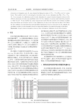
             失、气流再生噪声和全压损失系数的测定等效法》                                阵列式阻性消声器由吸声柱、外壳、支架杆组
             (GB/T 36079–2018)提出采用等效法测量阵列式消                    成,吸声柱在垂直气流断面上呈阵列式分布,吸声柱
             声器消声量,该方法需测量断面参数完全相同但                             两端装有导流罩,吸声柱横截面通常为矩形。阵列
             长度不等的 2 台消声器,根据测试结果确定阵列式                          式阻性消声器结构示意图见图1。
                                     W
                        b⊳  a  b                   ܱܧ                          L
                     bϕ⊳                           ࠮ืᎴ

                     aϕ
                                                    ծܦʹ
                     bϕ

                                                    ஃ౶ీ
                 H


                                                图 1  阵列式阻性消声器结构示意
                            Fig. 1 Schematic diagram of the structure of arrayed element dissipative silencer
   150   151   152   153   154   155   156   157   158   159   160