
Page 126 - 应用声学2019年第4期
P. 126
586 2019 年 7 月
Displacement Displacement
Step=1 Step=1
Sub=8 Sub=9
Freq=48.9519 Freq=96.3537
DMX=4.62687 DMX=4.61739
x x
z z
y y
(a) ഷ್വیവগ 1 ᄊॎ࿄ (a) ഷ್വیവগ 3 ᄊॎ࿄
5
8 4 3
ࣨ/10 -4 m 6 ࣨ/10 -5 m 2
4
1
2
0 0 0.1 0.2 0.3 0.4 0.5 0.6
0.1 0.2 0.3 0.4 0.5 ᡰሏ/m
ᡰሏ/m (b) ഷ್ᒭႀቫࣨᬤԍႃྟͯᎶᄊԫӑ
(b) ഷ್ᒭႀቫࣨᬤԍႃྟͯᎶᄊԫӑ
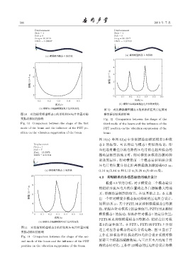
图 12 对比横梁模型模态 3 的形状和压电片位置对
图 10 对比横梁模型模态 1 的形状和压电片位置对横 横梁振动情况的影响
梁振动情况的影响 Fig. 12 Comparison between the shape of the
Fig. 10 Comparison between the shape of the first third mode of the beam and the influence of the
mode of the beam and the influence of the PZT po- PZT position on the vibration suppression of the
sition on the vibration suppression of the beam beam
图 11(a) 和图 12(a) 中分别描绘出横梁模态 2 和模
Displacement 态 3 的振型。可以得出与模态 1 类似的结论,即
Step=1
Sub=7 当把连有最佳分流电路的压电片贴在相应模态的
Freq=18.2976
DMX=4.61604 振动最强烈的地方时,则对横梁该模态的振动抑
x
制效果最佳,即对横梁前三个模态最佳粘贴分流
z
y
压电片的位置分别在距离横梁施加激励端 0.3 m、
(a) ഷ್വیവগ 2 ᄊॎ࿄ 0.14 m/0.44 m和0.12 m/0.28 m/0.48 m处。
10
4.3 抑制横梁的多模态振动的组合设计
根据 4.2 节的分析,对于横梁前三个模态最佳
8 的粘贴分流压电片的位置均在各自振幅最大的地
ࣨ/10 -5 m 6 方,即振动最强烈的位置。在这基础之上,本文提
如图 13 所示,其中 PZT1 用来抑制横梁模态 2 的振
4 出一个针对横梁多模态振动抑制的压电组合设计,
动,粘贴在针对模态 2 的最佳位置;PZT2 用来抑制
2
0 0.1 0.2 0.3 0.4 0.5 0.6 横梁模态 1 的振动,粘贴在针对模态 1 的最佳位置;
ᡰሏ/m
PZT3 用来抑制横梁模态 3 的振动,粘贴在针对模
(b) ഷ್ᒭႀቫࣨᬤԍႃྟͯᎶᄊԫӑ
态 3 的最佳位置。在 PZT1、PZT2 和 PZT3 上分别
图 11 对比横梁模型模态 2 的形状和压电片位置对横
连上对应各自模态的最佳分流电路。图 14 显示了
梁振动情况的影响
工作在 33 模态和 31 模态的压电组合设计系统对横
Fig. 11 Comparison between the shape of the sec-
ond mode of the beam and the influence of the PZT 梁前三个模态的减振效果,与三片压电片均处于开
position on the vibration suppression of the beam 路状态时对比,工作在 33模态的压电组合设计将横